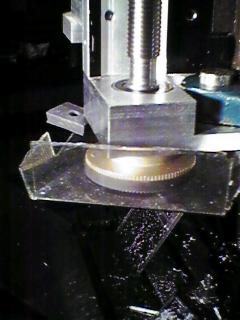
This bearing block is stepped so that it clamps below the lower stop-rod boss on the Bridgeport J-head main casting.
| |
The bottom of the ballscrew mount contains two angular contact
bearings to tightly constrain the leadscrew in the axial direction.
The bearing bore in the lower block has a step in the middle to
constrain the two bearings' outer races against inward pressure.
There is a flange, or step down in diameter, at the end of
the leadscrew, and part of the reduced diameter is threaded.
A threaded collar presses the outermost bearing's inner race towards the
inner bearing, applying preload to the pair of angular contact
bearings. The drive belt sprocket fits on the remaining end of the
leadscrew shaft.
This bearing block is stepped so that it clamps below the lower stop-rod boss on the Bridgeport J-head main casting. |
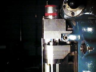 |
The upper block is similar to the bottom in the way it mounts to
the J-head casting. It only contains one radial contact bearing
which allows the leadscrew to expand or contract without restraint.
It has a helically-slotted coupling to the encoder, and a
fine sprocket drive for the tachometer (which can't be seen in
this view, as it is behind the block).
You can also see the one-piece adapter that goes from the ballnut flange to the quill. It takes a large bolt that connects it to the quill, at the location the quill stop ring normally mounts. The ballnut is actually inside the adapter, the ballnut flange can be seen on the bottom of the adapter. |
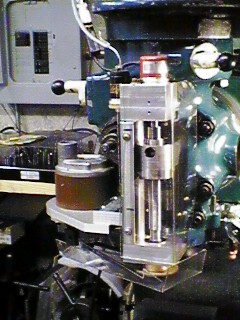 |
In this front view, you can see the large hole where the bolt that mounts the adapter to the quill passes through. This requires the ballscrew and nut be removed. The tachometer (black) can be seen to the left of the encoder (red). The drive motor (brown) is on the left. The two small holes in the front of the upper block allow the encoder's coupling to be tightened when everything is aligned. This block splits into 2 pieces to allow the tach belt to be installed. A clear plastic cover wraps around the front and right of the ballscrew area to keep chips off the screw. The black lines marked on the vertical bar mark the travel limits of the quill. |
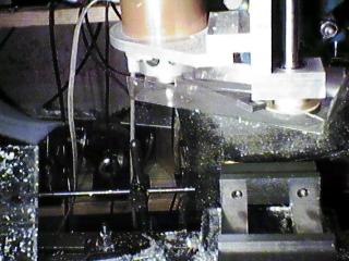 |
This is a view of the z axis drive mounting. A rounded piece was made to support the motor, and slots allow it to slide forward and backward to set belt tension. A plastic guard keeps debris and tools out of the belt and sprockets. |