| |
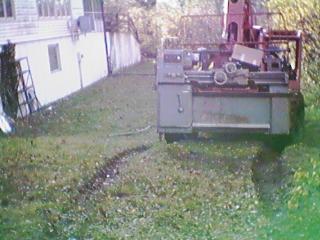
Here's the lathe, just off the flatbed truck, backing down the back driveway toward the house. Everything looks real good so far. The forklift is a Lull 644B-42 reach construction lift. A marvelous machine, but at 21000 Lbs. it is rather heavy. |
 |
Suddenly, progress stops. I look down, and the ground looks closer! OH, no! Mired up to the axles! |
 |
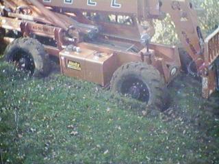
Well, I was too busy getting the thing out to take many more photos. I used the lathe as a dead weight to tip the lift truck forward so the rear wheels were up in the air. We then packed mud under the wheels and covered it with 3/4" plywood. I then used the boom to press down on the ground to lift the front wheels. There was a hydraulic relief in the system, so somebody had to stay in the cab with the engine running holding the joysick to keep the wheels up. Pretty hazardous, but there was no other way we could think of. I turned $150 of 3/4" plywood into toothpicks! |
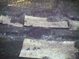 |
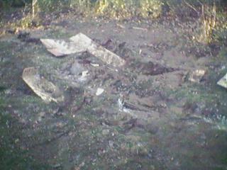
And, one more view of the wreckage of my back yard. Fortunately, we have about 5 months before we have to think about mowing this "lawn". looks more like the mountains on the moon! |
 |
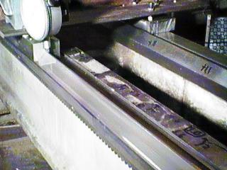
Here's the photo from Machinery Values that went with the eBay auction for this machine. Obviously, they have a much better digital camera than I do! Note the two cranks on the QC gearbox. It provides 80 threading feeds, and 80 different carriage feeds through the drive shaft. Both carriage and cross feeds are powered through multi-plate clutches, rather than by engaging sliding gears. These are adjusted to slip when overloaded. The left side of the feed shaft has U-joints in it, so it does not deflect the carriage while rotating. |
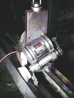 |
And now, bad news! After getting it inside, and cleaning it up a bit, I discover that the front inverted-V way has .013" wear, and the back, flat way has only .002". That tips the carriage enough to cause about .016" of error on a 1" diameter piece! After thinking about the problem for a while, I discover the tailstock ways are in pretty good shape, under .001" wear, but a lot of dings and mars. So, I rigged up this contraption to grind the main ways, using the tailstock ways as a reference. This is the tailstock base, with an angle plate bolted on top of it. The compound slide is mounted on that, so it can move vertically. On that, I have my toolpost grinder. I would need to make the T-nut to mount it on the compund anyway, so I made it now. I can swing the toolpost grinder one way to dress the wheel, then swing it down to grind the ways. I got the V-way error reduced to under .002". I then started spotting it with a straightedge and grinding down the high spots with an air die grinder and Cratex wheels. At first it looked like it was working quite well, although a little slowly. Then, I realized I was getting a very lumpy surface, with lots of little 1/8 to 1/4" hills and valleys. I switched to a 2" Cratex wheel 1/2" wide, which did better, but it just wasn't improving the flatness, it was making it worse. So, I got out some bench stones and started rubbing them on the ways. This was REALLY slow, but it was improving flatness, and when used with the spotting dye and straightedge, was correcting the large-scale high spots without making lots of small ripples. I got some more bench stones in different abrasives and grit sizes, and rub them together with oil to keep them flat. Some of the Silicon carbide stones have VERY soft bonding, and just crumble away amazingly fast. They do remove metal pretty fast, however. The alumina stones seem harder, and tend to glaze pretty easily, but rubbing two of them together quickly restores the abrasive surface. When I get really close to flat, I switch to an India stone, that is quite hard, but produces a mirror finish, and leaves no grit embedded in the ways. Front error is down to about 0 + .0005", back error is about 0 + .001", that's where I'm working right now. |
 |
This is a view of the inside of the headstock, with the top cover "hinged" open. The bull gear is at the right. Note the channel that will end up just above the bull gear when the top is closed. It captures oil slung up by the bull gear and routes it to the trough seen at the left of the headstock. This has strategically placed holes to allow the collected oil to drain onto bearings, the backgear shaft, etc. You can't really see it in this picture, but the Sheldon has a very interesting headstock design. The drive motor in the base has a 4-speed gearbox directly mounted to the motor. Three large V belts drive a shaft that is coaxial to the spindle, but runs on separate bearings. In direct drive, this shaft drives the spindle through clutch teeth, so the spindle does not pick up gear vibrations. (In back gear, there is gear drive to the spindle, but the lower speeds may cause vibrations to be minimal.) |
 |
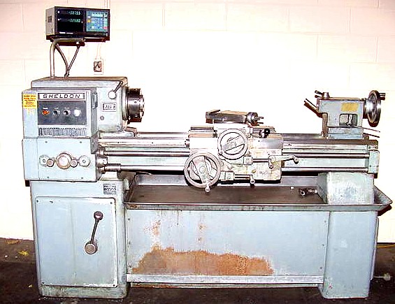
Here is a picture of the carriage gauge I threw together to "scan"
the bed. The beam is just a piece of BIG angle iron. On the
front, inverted-Vee way, there is a block with a matching machined
and scraped Vee. On the rear flat way, there is a hand scraped
flat on a 'tripod' arrangement of 10-32 screws, with jam nuts
above and below the angle iron. This allows me to tilt the
beam until the Vee rides properly on the front way by raising
or lowering all 3 sets of nuts equally, and then adjust the
tilt of the flat pad by differential adjustment of the 3
sets of nuts. The front Vee block is mounted securely to
the beam, as there is no need to adjust that angle.
You can see the dial indicator on magnetic mount setup to
read from the top of the reference surface (the flat on top
of the Vee way).
The bad news is that this fancy measuring instrument combines errors from front and back ways, making it impossible to properly determine how flat EITHER way is! UGH! I finally figured out using a large ground square and mounting the indicator to that and sliding it down the reference surfaces makes it possible to check each way separately. This mistake cost about 2 months, and ended up messing up the nearly straight rear way. I now have it back to flat within +/- .0002" most of the way. I'm just cleaning up a few small deviations and I will finally be able to move on to the front way. Once the back is truly flat, the carriage WILL be able to measure the front properly. |
 |
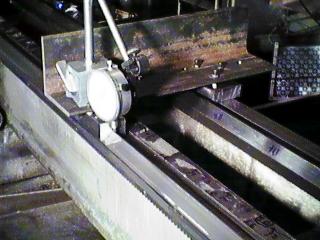
A closeup of the bottom of the assembly, you can see the Vee block and flat better in this shot. |
Well, it gets worse and worse! I spent MONTHS working to higher and higher precision following a faulty reference. I lucked into a Talyvel precision level on eBay for about 12 cents on the Dollar. It is vastly more sensitive than a master precision level, and settles much quicker, too. I was immediately able to see that the reference surface was not flat, but had a sag of about .003" in the middle. So, I had been putting a big sag in my carefully scraped surfaces. I started over almost from scratch, but at least I now had a measuring instrument that would tell me what was going on for real!
Several months later, I have the rear way flat to about +/- .0001" over 6 feet, and the front way flat to about the same, and parallel to the rear within +/- .00005" or so, and also following my corrected front reference surface to about +/- .00005".
I have now applied Moglice to the underside of the carriage. First, I drilled and tapped 8 10-32 holes in the carriage, so that brass-tipped set screws could be used to set the carriage at the correct height, and also set the front back position and alignment with the spindle. I goofed the first time, and put way too little of the putty-hard formula on the ways, and it left voids and low spots all over the place. I had to break out all the air bubbles, rough up the low spots, and apply a 2nd 100 g batch of Moglice. This time, I got enough Moglice on there, and it made a good imprint of the bed. Since the 2nd application spread over the first a bit, there were slight variations in height, and so I have had to scrape the Moglice down. This goes pretty fast, though.
While fixing some other things on the lathe, like the totally blacked-out oil sight windows, I discovered a broken gear tooth on a gear in the QC gearbox. This is the most complicated QC I've ever seen. It looks like the inside of an automatic transmission, with needle roller bearings and ultra-thin roller thrust bearings everywhere. (It does provide 80 different threading feeds, so it has to be a bit complicated.) I drained the oil (all over the floor, after I dropped the drain plug into the funnel, plugging it up and making it overflow) and then retrieved the broken tooth. I dismantled the box to pull out the shaft with the broken tooth, and brazed it back on. I'd never brazed a gear tooth before, and it was a comedy of errors. I knew I'd have heat problems, so I rigged a propane torch to preheat the gear, and when it stopped smoking, I fired up the Oxy/MAPP torch and tried to get it hot enough to melt the brazing rod. It took forever, I was constantly worrying I'd run out of Oxygen just when it got hot, but I managed to do it! I then made a single-tooth profile cutter and put it in my flycutter, as I didn't have a gear cutter that was even close. I cut the excess brazing material as close to the right shape as I could, first lining the cutter up between the remaining teeth, then turning the dividing head to the next space and cutting the braze. The gear didn't quite work right, so I had to mark all over the repaired area with a Sharpie marker and then run it back and forth against the other gears, and then examine for the spot where the marker was wiped off. This actually worked, and I was able to shave it down, using a broken hacksaw blade as a tiny scraping tool. The gear now seems to run as freely, and as smoothly as the others. Oh, yeah, I called DeVlieg/Bullard, this gear/shaft part is $425, and they will have to make it for me! Yikes, only as a last resort, if my repair fails, and I can't make the whole gear from scratch.
I'm also cleaning the one-shot oiler's metering orifices with solvent, and will have to check them after a few days. I think they may have gotten blocked, and that's why the lathe had so much wear.
I was not able to salvage the metering orifices, so I had to buy new ones. I shouldn't have to worry about them clogging up again for a while.
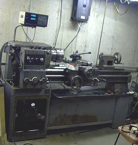
And, finally, the completed lathe in it's new home. Thanks to Fitch Williams for the VFD hanging on the wall above the lathe! It runs great. I added braking resistors and a jog button on the lathe's control panel. The jog is great when shifting hi/lo on the headstock, and when the quick-change doesn't want to engage. The braking of the VFD is nice, it stops the lathe, even from high speed, within one second.
 |
Hey, an interesting note! The manual and lube plate has the wrong info for the headstock! It says to use Mobil Vactra oil heavy for the standard-speed headstock. This sounded wierd to me, way oil in the spindle, gear oil on the ways, but the factory ought to know, right? Well, I had a severe bearing overheating problem at 1250 RPM, and after some internet discussions, I decided that the manual had to be wrong, there's no way that extremely heavy way oil should be in a roller bearing machine tool spindle. So, I changed to Mobil Velocite No. 6, which is about as thin as water. That is the specified lube for the high speed version of the lathe. it is about 1/20th the viscosity of the other one. It is confirmed by later manuals that the factory meant to specify Velocite heavy, but wrote Vactra heavy by mistake. |
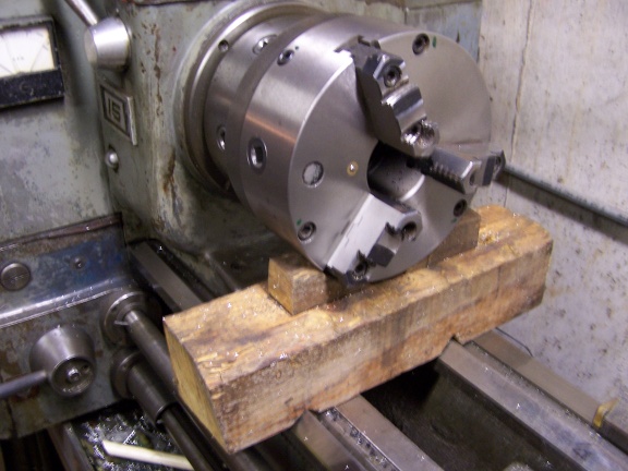 |
Here's a "chuck handler" that helps me put the chuck on and off the lathe. The 4x4 is fitted with Vees on the bottom to clear the bed. Then, it has some wedges to keep the chuck from rolling off the 4x4. You set this under the spindle face, set the chuck on it and then turn the spindle to align the camlock holes. Then, just slide the chuck onto the spindle. MUCH easier than having to hold it in the air! |