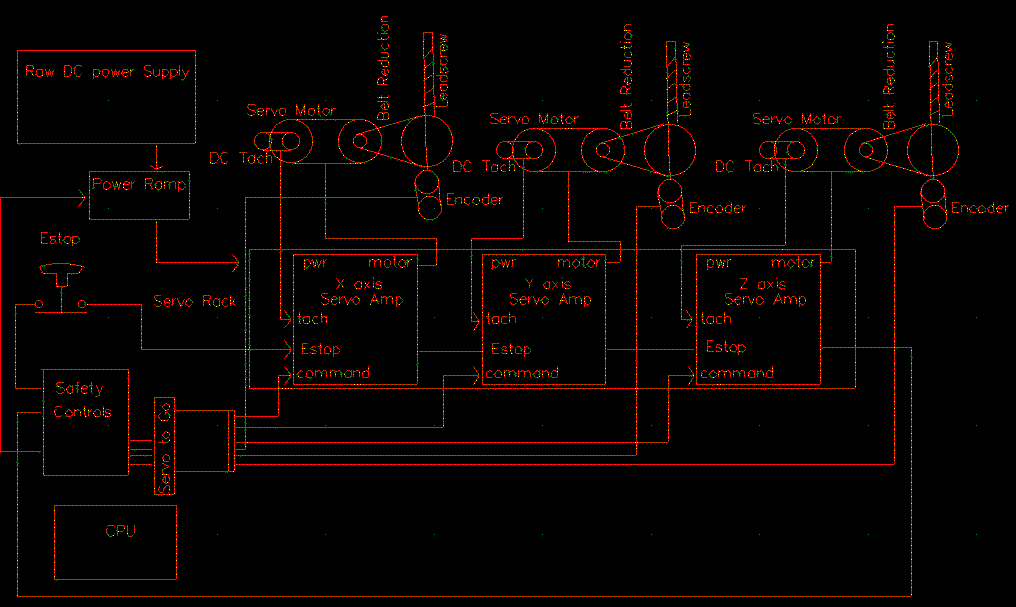
A CNC Block Diagram
This is a block diagram of my CNC system. It shows the
CPU, and the Servo-to-Go card that is plugged in to an
ISA slot in the motherboard. That card feeds +/- 10 Volt
analog velocity signals to the servo amps. It also receives
signals from the quadrature encoders on each axis.
The servo amps drive the motors, and sense velocity
from the DC tachometers reading leadscrew rotational
velocity. Each servo amp has a fault relay that opens
if the amp has been overloaded or otherwise is no longer
following commands from the CPU. These are wired in series,
and then in series with the Emergency Stop buttons. If
any of these contacts opens, it tells the CPU to E-stop,
and also shuts down power to the servo amps, and extracts
any energy provided by moving parts of the machine.

