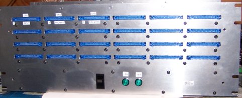
The inputs, prompt outputs and one of the delayed oututs are on the front of the unit, the remaining delayed output is on the back, as is the power input. The unit will run from 120 or 240 V mains supplies.


 |
The Amplifier Splitter Delay is a 19" rack-mounted unit that provides 128 channels of signal amplification, with three outputs from each channel. One output is prompt, meant to be used for a discriminator. There are two more outputs that are delayed and attenuated, meant for charge integrating ADCs. The delays are created with electromagnetic delay line components in compact SIP packages. These are socketed, so the delay can be changed to suit the equipment.
The inputs, prompt outputs and one of the delayed oututs are on the front of the unit, the remaining delayed output is on the back, as is the power input. The unit will run from 120 or 240 V mains supplies. |
 |
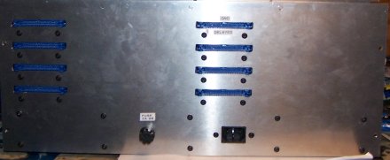
This is the rear of the unit, showing the output connectors and power input. |
 |
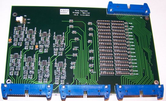
This is one of the 16-channel boards. The front connectors are, from the left: input, prompt output, and first delayed output. The rear connector is the second delayed output. Looking at each connector, the first signal pin is at the lower left. The top row of pins are grounds. The last two pins to the right are not used. |