This amplifier takes in a +/- 10 Volt analog velocity command from the CNC control, and causes motion such that the velocity as measured by a DC tachometer proportionally matches the command. There are LED bar graph displays of commanded velocity and motor current. The amplifier is rated at 10 Amps and 96 Volts. The output is fused as a final safety measure, but there is an electronic overcurrent protection, that will shut the amplifier off immediately in case of a shorted or overloaded output, or output shorted to ground. If the overcurrent limit is reached, a red LED lights, and a relay is tripped to inform the CNC control that the amplifier has shut down. If 12 Volt DC power to the amplifier fails, then it will also signal shut down. An enable input is provided for the CNC control to enable and disable the amplifier.
The PWM frequency is set at 100 KHz to minimize the size of the output filter components, and to maximize amplifier bandwidth. The output filter removes the 100 KHz PWM carrier, so that it does not radiate, or affect other nearby circuits, such as position encoders. The 4 power transistors are IR HEXFETs, and are very efficient at fast switching, so that very small, sheet-metal heatsinks are sufficient.
The amplifier is built on a 4.5 x 6" circuit card, with a 22/44 contact card-edge connector on one end. All connections are made through this connector. Because of the heat sinks and filter components, the amplifier takes about 2" of space in the 'thickness' of the board.
| |
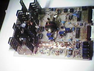
This is a closeup of the servo amp PC board. This one was a hand-made prototype. Later units have a manufactured PC board, with component designations silk-screened on, solder mask, and gold-plated edge connector fingers. |
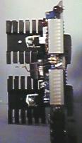 |
This is a closeup of the front of the servo amp board, what serves as its' front panel. The upper LED bar graph shows motor current, the lower bar graph shows the velocity command coming from the CNC control. There are arrow LEDs below the bar graphs which show the polarity of the magnitude indicated above on the bar graph. There is a fault reset button on the bottom right side of the board. Numerous adjustment pots are on the board, the most frequently needed right on the front edge, as seen at the lower left. A red fault LED is at the upper left. |
 |
This is an Xgraph screen shot of a position (actual vs. requested) log trace from EMC, with a move commanded at 90 IPM. You can't really see the requested, the slightly fuzzy actual trace covers it. But, the actual follows the requested position very closely. This is from the X axis of my Bridgeport mill, driven by the Pico Systems servo amplifier. The X axis of this plot is time, at 1000 samples/sec, for 3 seconds of real time. The Y axis is in inches, showing a move of about 2.4" |
For more information, contact :
Jon Elson
Pico Systems
543 Lindeman Rd.
Kirkwood,  MO  63122
(314) 965-5523
or, email at : elson@pico-systems.com