 Board Layout
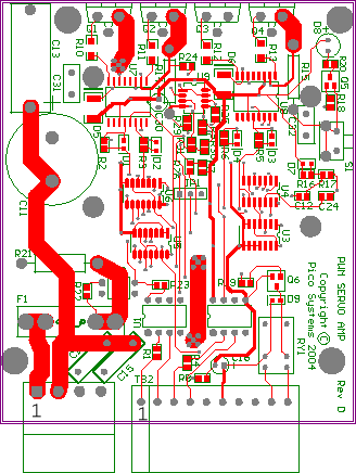
| TB1 is the motor and motor power connector. Pin 4 is closest to the 10-pin connector. | |||||||||||||||||||||||||||||||||
| Pin # | Signal |
| 1 | Power + |
| 2 | Power Ground |
| 3 | Motor + |
| 4 | Motor - |
| Pin # | Signal |
| 1 | PWM + |
| 2 | PWM - |
| 3 | Direction + |
| 4 | Direction - |
| 5 | Enable |
| 6 | + 12 V Power |
| 7 | I Lim Set |
| 8 | Not Fault - |
| 9 | Not Fault + |
| 10 | unused |
| PWM + and PWM - are the input connections to an optocoupler.
A 1000 Ohm series resistor is provided, as this device only needs
about 3 mA to be turned on. Direction + and Direction - are set up
the same way.
The Enable signal is loaded to ground with a 3.3 K Ohm resistor. Connecting it to +12 V enables the amplifier. Leaving it undriven or gounding it will disable the amplifier, turning all transistors of the full bridge off. The body diodes of the FET devices will still allow a braking resistor to brake the motors with the amp in the disabled state. This is more gentle than stopping the PWM signal at the PWM input, while leaving the amp enabled, which will effectively short the motor. The +12 V input is the power to the control logic of the amplifier. The power consumption is less than 100 mA for each axis. A regulated supply is recommended, as the power FETs should not be exposed to excessive gate voltage, and the logic chips in the amp are rated for 15 V maximum. The I Lim Set terminal is used to set the cycle-by-cycle current limit threshold. It is pulled to ground by a 3.3 K Ohm resistor, and the threshold is 5 mV per Ampere of output current. So, for a limit of 10 Amps, a resistor of approximately 290K Ohms would be used. The formula is: Rilim = 2900000 / Current Connect this resistor between terminals 6 (+12 V) and 7. There is a solid state relay that connects an (external) positive source on TB2-9 to a sink at TB2-8 when the amplifier has power and is not in a fault condition. These opto-isolator outputs are fully isolated, so they can be connected in series in the E-stop chain. It will open this circuit if a fault condition occurs or if the +12 V power to the servo amp is shut off. A fault condition will occur if the amplifier draws more than 20 Amperes from the motor power supply for any reason. One possible cause is a short to ground of the motor or motor cable. Another cause is a transient short in the motor, or a sudden increase of the PWM duty cycle, especially when the I Lim Set resistor configures the amp for a current limit near 20 Amps. (This should be a rare occurance in a well-tuned servo system.) The fault condition can be reset by pressing the reset button on the amp, taking the Enable signal to ground and back to +12 V, or removing +12 V power from the amp and restoring it. |
| Board Layout |