|
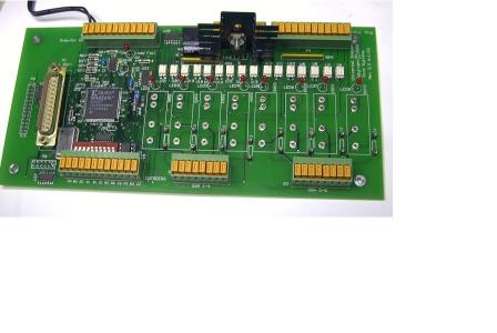
The Universal Stepper controller is a small board with everything
needed to control a 2-, 3- or 4 axis machine tool with stepper
motors except for the stepper drivers. It contains 4 digital rate generators to provide very smooth
changes in step rate, 4 digital counters to count the step pulses, or
alternatively encoder pulses, 16 channels of opto-isolated digital
inputs, and 8 positions for Solid State Relays of your choice to
be mounted. It is connected to a computer by the parallel port.
The parallel port must be at least capable of bi-directional exchange
of data, but EPP or ECP modes give the best data transfer rate.
The digital I/O section also implements emergency stop logic.
There is an on board watchdog timer, which can be set to cause an
emergency stop in case the computer fails to update the rate generators in a
timely fashion. This could shut off the stepper drivers, spindle
motor, coolant, etc. For machines with more than 4 axes, 2 or more
boards can be used together.
This board makes any step/direction drive appear to the computer as
a servo system. Even if encoders are not used, the step rate generators
provide a simulated encoder signal for the encoder counters to count.
The computer reads the position from the encoder counters and computes
a new velocity command to send to the rate generators. This takes only
about 50 uS on a 333 MHz Pentium II, so that reasonable servo update
rates of 10 KHz could be made on such a machine. I usually use 1 KHz,
because that is all that seems needed for machine-tool type applications.
This has nothing to do with step rates, however, as the board can still
output smooth pulse trains at 300,000 steps/second. This way, a
modest computer can perform at much higher step rates than a
high-end computer using software generated step pulses.
The stepper rate generators divide a 10 MHz crystal clock by a minimum of 2 up to
224-1, which comes out to 5 MHz down to .596 Hz.
These rates are adjustable in 100 nS steps, so extremely precise
acceleration and deceleration ramps can be generated to allow the
greatest speeds before the steppers stall or lose steps. Substantial
logic prevents the direction from changing too close to a step pulse,
and vice versa. The amount of setup time, and the width of the
step pulses are individually programmable in 100 nS increments, from 200 nS
up to a maximum of 25.5 uS. An additional switch setting makes the
direction signal change state only at the beginning of a step pulse.
This is the desirable mode for Gecko Drives.
The stepper outputs are available in both step/direction and
full step phase signals. The phase signals are identical to
the signals produced by a quadrature encoder, and are also fed
to the encoder counters in systems where encoders are not used.
These stepper ouputs are capable of sourcing or sinking up to 24 mA
to drive opto-isolated inputs on your stepper drivers.
The encoder counters keep a continuous watch over the encoder signals
(or rate generator phase signals) and can count up to 250,000 steps/second
or encoder counts/second, per channel. They can also sense the
index pulse from an encoder, or a home position switch or optical
sensor for precise stepper homing without encoders.
The digital input section has 16 optoisolators which can sense
the condition of switches, relays, pressure switches, float
sensors, etc. to allow the machine to be stopped if a fault condition
occurs, sense when an axis is close to the travel limit or home
position, etc. The board provides isolated 5V power to power
the switches and/or sensors.
The digital output section provides sockets for up to 8 Crydom or equivalent
Solid State Relays such as the D2W202F (240VAC 2A) or the CMX60D5 (60V DC 5A)
to be mounted directly onto the
board. Note these particular SSRs are compact, and some older models
may not fit the space on the board. Pico Systems also makes a signal-level
DC SSR for controlling VFDs and other electronic loads, up to 24 V and
15 mA. These sites are left unpopulated to allow the user to
select SSRs with the output configuration and current capacity
needed. A terminal strip is provided for connection to the
outputs of the SSRs. LEDs monitor the command signal to each of
the SSRs. A fuse position is included next to each SSR to protect
the board traces from severe shorts.
The last digital input is configured to monitor an emergency
stop chain. A series circuit of normally-closed switches breaks
the continuity of the circuit when an unsafe condition or problem
develops (ie. spindle motor stall, stepper driver overheat, lube
level low, manual E-stop switch activated, etc.) An analog timer
circuit can also monitor the flow of commands from the computer, and
if the computer ceases updating the rate generators, then an E-stop
can be caused. The E-stop condition turns off all signals to
the solid state relays, as well as stopping the stepper rate generators,
to bring the machine to a safe stop.
You need to provide a 'wall-wart' type plug-in power supply
capable of delivering 9 - 12 V DC at 300 mA. It does not
need to be regulated. It is to be connected to P2 terminals
labeled G and PWR, with G being the minus of the supply, and
PWR being the plus.
The Universal Stepper Controller takes advantage of the IEEE-1284 hardware signalling
protocol, allowing multiple register addresses to be selected and
transfers accomplished with minimum CPU overhead, and maximum
data transfer rate. This requires a parallel port that can
operate in the ECP or EPP mode. It is possible to use any
bi-directional parallel port at the cost of additional CPU overhead (but, not supported by the LinuxCNC driver).
Note: You MUST use a cable marked "IEEE-1284 compliant" for this board to work reliably.
Also, if using a PCIe parallel port card, it has been discovered that Startech, SIIG and Rosewill cards with the OXPCIe952 chip will not work with LinuxCNC versions before 2.7.8 (March 14, 2017) . (PCI (not express) cards from SIIG have worked fine for years.) The Saba PCIe card with the NetMos MCS9900 chip has been verified to work, as well as other PCIe cards with the MCS9900 and MCS9901 chips.
Pico Systems is currently delivering this board at an end-user
cost of US $250.
Sample configs files for LinuxCNC using the Universal Stepper board
Sample configs files for LinuxCNC using the USC with the spindle DAC
Sample configs files for LinuxCNC using the USC with 8 extra digital outputs
Sample configs files for LinuxCNC using the USC with Spindle Sync for threading
Connector Pinouts for the Universal Stepper board
Register Definition for the Universal Stepper board
Switch Settings on the Universal Stepper board
Parallel port compatibility and options
Download Linux diagnostic program
for Universal Stepper Controller.
How to install and use the diagnostic program.
Sample wiring for the Universal Stepper board and Gecko 200-series stepper drives
Sample wiring for the Universal Stepper board and Gecko 251X stepper drives
Sample wiring for the Universal Stepper board with the Gecko servo interface
Sample wiring (generic) for the Universal Stepper board
Dimensional drawing of the Universal Stepper board
Price List
|