| JP9 | JP10 | JP11 | resolution Lines/Rev |
| IN | IN | IN | 1000 |
| OUT | IN | IN | 2000 |
| IN | OUT | IN | 2500 |
| OUT | OUT | IN | 3000 |
| IN | IN | OUT | 10000 |
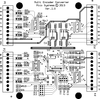 | Board Layout |
connections for encoder with 17-pin connector
| P1 is the quadrature encoder input. |
|
||||||||||||||||||||||
| P2 is the input for the special Fanuc Commutation signals.
Pins are as follows: |
|
||||||||||||||||||||||
| P3 is the output for the regenerated quadrature encoder signals.
Pins are as follows: |
|
||||||||||||||||||||||
| P4 is the industry-compatible Commutation (Hall) signal output.
Pins are as follows : |
|
| Jumpers JP1, JP2 and JP3 should be to the right (away from P1). JP4 - JP8 should be to the left (toward P2). When jumper JP12 is installed, the converter will not use the quadrature encoder to refine the commutation, but will only use B1 - B4 signals. This will lead to rough motor operation. It is useful if there is a question of whether the correct encoder resolution has been selected with jumpers JP9 - JP11. With JP12 removed, the converter will switch to using the quadrature encoder count as soon as it sees the first index pulse. Later revision boards also have a JP13 which should be installed for standard encoders and removed for "ABS" encoders. |
| LED D4 (green) indicates that the encoder index pulse has been detected, and the quadrature encoder count is being used to generate the commutation signals. When D4 is dark, it means that the index has not yet been detected since power on, and the Fanuc proprietary signals B1 - B4 are being used to generate the UVW commutation signals. D3 shows the state of the U output. D2 shows the state of the V output. D1 shows the state of the W output. |
| JP9 | JP10 | JP11 | resolution Lines/Rev |
| IN | IN | IN | 1000 |
| OUT | IN | IN | 2000 |
| IN | OUT | IN | 2500 |
| OUT | OUT | IN | 3000 |
| IN | IN | OUT | 10000 |
| | Board Layout |
connections for encoder with 17-pin connector