| P2 is the serial encoder input. |
|
|||||||||||||||||||||||||||||||||||||||
| P1 is the output of quadrature encoder signals and
commutation signals. Pins are as follows : |
|
|||||||||||||||||||||||||||||||||||||||
| LED D2 (green) indicates the converter has power.
LED D1 (red) indicates the converter is not receiving a valid signal from the encoder. |
| 1 | 2 | 3 | resolution Counts/Rev |
| ON | ON | ON | 32K (32768) |
| OFF | ON | ON | 64K (65536) |
| ON | OFF | ON | 128K (131072) |
| OFF | OFF | ON | 256K (262144) |
| ON | ON | OFF | 1024K (1048576) |
| Switch 6 off for Absolute (A) encoders |
| Switch 7 off to invert Hall (commutation) signals |
| 8 | 9 | MHz |
| OFF | OFF | 0.5 |
| OFF | ON | 1 |
| ON | OFF | 2 |
| ON | ON | 4 |
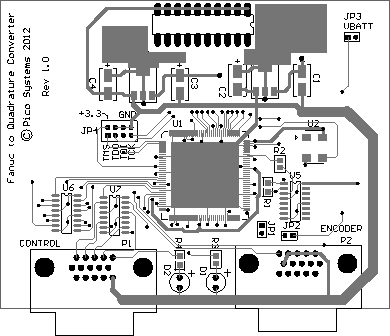
| | Board Layout |