 Board Layout
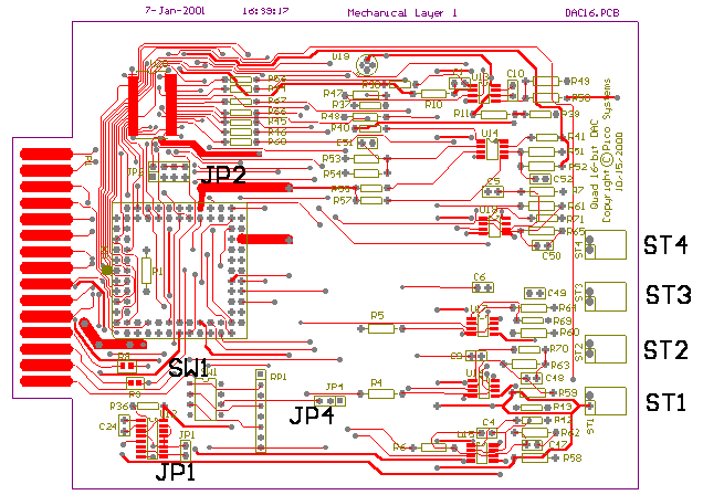
The DAC16 occupies a block of 16 consecutive addresses on the EPP (IEEE 1284 protocol) bus. The high 4 address bits are specified through a 4-position DIP switch marked SW1. The Most significant bit (bit # 7) is switch 4, the least significant fixed address bit (bit # 4) is switch 1.
| ST1 through ST4 carry the single-ended voltage outputs. ST1 is for channel 0, the first Axis. St4 is for channel 3, the last Axis. With the component side of the board UP, and these connectors facing you, Ground is on the LEFT, and the voltage output is on the RIGHT. |
| JP1 should be vertical (as the board is shown in the drawing below) to disable the watchdog timer. It should be horizontal to allow the watchdog timer to detect a failure of the computer to update the DACs in a reasonable time. |
| JP4 is factory set to cause a watchdog timeout to set all DAC outputs to Zero volts. Cutting the board track between pins 1 and 2, and jumpering pins 2 to 3 will select a watchdog timeout to set all DAC outputs to -10 V, but that is not likely to be useful. |
| All JP2 pins should be jumpered vertically (as the board is shown in the drawing below). This jumper field is only for reprogramming the CPLD chip U3. |
| Board Layout |