PPMC Encoder Board
Features :
The Parallel Port Motion Control Encoder board has 4 24-bit
quadrature encoder counters. The board provides up to 200 mA
at 5V to each of the 4 encoders through resettable (PTC)
fuses.
There are two versions of the encoder board available, one supports
only single-ended encoder inputs, the other will support both
single-ended and differential encoders in any combination.
The choice between single-ended and differential inputs is
made through jumpers, on a channel by channel basis.
The Encoder is capable of generating a servo cycle clock
that can be selected under software control from 625 Hz to 10 KHz
in 16 steps (10 KHz divided by a factor of 1 to 16). This
clock can be provided to additional encoder boards and DAC16
boards, so all encoders and DACs sample and update synchronously.
The encoder board occupies a block of 16 consecutive addresses on the
EPP (IEEE 1284 protocol) bus. The high 4 address bits are
specified through a 4-position DIP switch marked SW1.
The Most significant bit (bit # 7) is switch 4, the least significant
fixed address bit (bit # 4) is switch 1.
Connectors :
P2 through P5 connect to the encoders.
P2 is for channel 0, the first Axis. P5 is for channel
3, the last Axis. With the component side of the board
UP, and these connectors facing you, pin 1 is on the
Left. Pins are as follows :
| Pin # | Signal |
| 1 | +5 V |
| 2 | Ground |
| 3 | A |
| 4 | B |
| 5 | Z |
| 6 | A/ | Differential Only |
| 7 | B/ | Differential Only |
| 8 | Z/ | Differential Only |
| A and B are the quadrature signals from the
encoder. If you have an encoder with an index
channel, this is connected to the Z input.
For differential encoders, the A/ B/ and Z/
inputs are used for the complemented signals.
|
| JP13 is factory set for normal operation. It can
be broken to allow downloading the FPGA program
from a computer during debugging. With the jumper
in the factory (closed) state, the FPGA downloads its
program from the SPROM in U2. A failure of the
FPGA program to correctly load is indicated by a
steadily lit LOAD FAIL LED. If the program does
not load correctly (this should not happen in the field)
it could be due to slow or erratic rising of the
+5 V power supply.
|
On boards which have the differential input option,
the following jumper positions are used to select
input mode for individual channels. Single-ended
is selected with the jumpers to the left (as the board
is shown in the drawing below), and differential
is selected with the jumper to the right.
| Channel # | Jumpers |
| 0 | JP1, 2 & 3 |
| 1 | JP4, 5 & 6 |
| 2 | JP7, 8 & 9 |
| 3 | JP10, 11 & 12 |
|
|
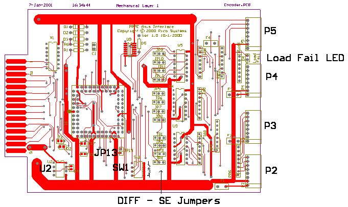 Board Layout Board Layout |
|
To Home