Pico Systems has developed a low-cost servo amplifier to drive brushless motors of a motion-control system. It uses PWM (Pulse Width Modulation), a technique to reduce power dissipation in the amplifier to a minimum.
Any motor providing the industry-standard 3 commutation "Hall" signals can be used with this amplifier. Some motors combine these signals into their encoder, other have actual Hall sensors inside the motor's housing. Note that some proprietary motors use other schemes to derive the commutation signals, such as Yaskawa. Contact Pico Systems with your motor information to assure compatibility. (Note: Works GREAT with Pittman 4000 series motors, Giddings & Lewis Centurion SSM series, SEM HJ-series motors, IMTTUSA BLDC34F series motors, Fanuc red cap and the Keling KL23BLS series!) We have a commutation signal converter for the Panasonic MUMS-series motor available, and also for Fanuc red-cap motors with incremental encoders (Pulse Coder).
This amplifier takes in opto-isolated PWM and direction signals from a motion controller, and produces a filtered PWM drive waveform to the motor. It can operate from up to a 160 V DC power source, and can deliver up to 20 A to the load. It has user-settable cycle by cycle current limiting, and a separate, high-side overcurrent detector. If the overcurrent limit is tripped, the amp goes into fault status, a red LED lights, and an optoisolator signals the problem to the controller.
The PWM frequency is determined by the motion controller, but should be between 25 and 100 Khz. The duty cycle can be reduced to zero, but must not reach 100%. Off time of at least 500 nS must be provided every cycle to recharge the "bootstrap" capacitors in the high-side transistor's gate drivers.
The polarity of the PWM pulse is set by default such that no current in the input to the optoisolator equals no current at the output of the amplifier. Normally, the input terminals to the optoisolator can be rewired to provide the opposite signal polarity. In cases where the motion controller lacks source or sinking capability, an optional jumper can be used to reverse this polarity on the amplifier.
IMPORTANT NOTE: The main motor power supply must be OFF when the 12 V power to the board is first turned on, otherwise transistors can be damaged. The best way is to have the motor supply switched by a solid state relay controlled by the out-of-Estop logic.
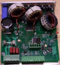
The amplifier is built on a 3.9 x 4" circuit board, with a metal bracket supporting the board and power transistors. The part of the plate where the transistors are mounted is intended to be bolted to a heat sink, but in low-current applications, the metal plate may provide sufficient heat removal. The entire volume taken by the amplifier is 1.5 x 3.9 x 4.25"
Connector Pinouts for the PWM Servo Amplifier
Wiring for Fanuc "Red Cap" brushless servo motors with 17-pin encoders
Wiring for Fanuc "Red Cap" brushless servo motors with 19-pin encoders
Wiring for Keling brushless servo motors
Wiring for IMTT-USA (Wantai) brushless servo motors
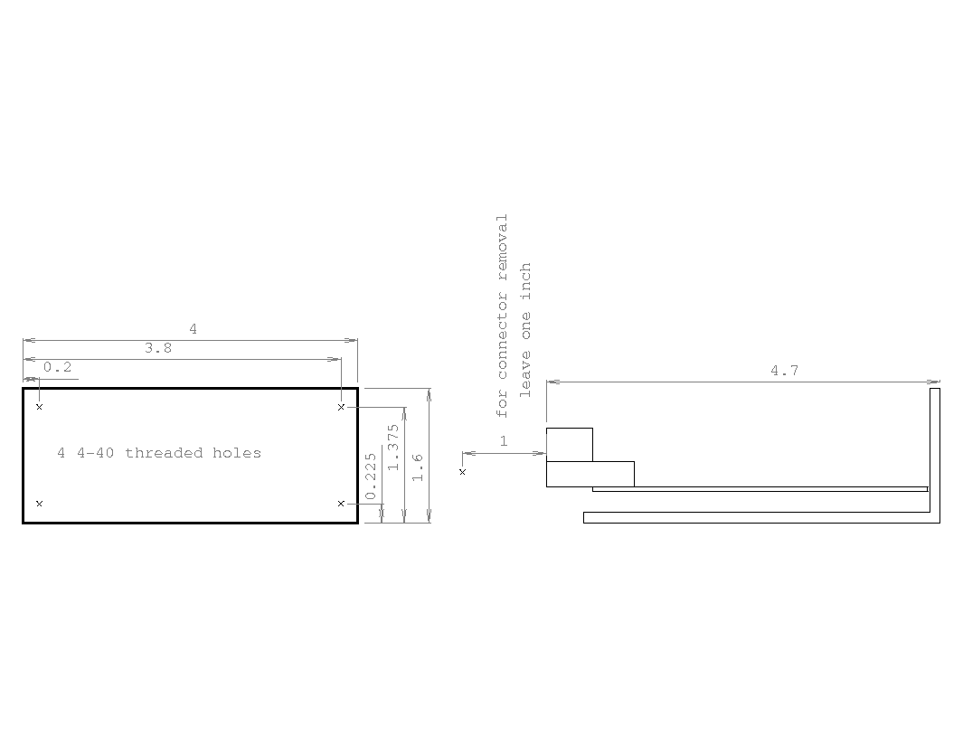
Mechanical drawing for servo amp
pre-machined heat sinks for the PWM servo amplifier
For more information, contact :
Jon Elson
Pico Systems
543 Lindeman Rd.
Kirkwood,  MO  63122
(314) 965-5523
or, email at : elson@pico-systems.com